4 DOF Timoshenko element shape functions
Plotting the shape function of 4 DOF Timoshenko elements using the github example code.
The track model implemented here is based on the work of Gimenez et al [Gimenez2018]. The finite element implementations feature two choices of Timoshenko beam elements:
The conventional 4 DOF Timoshenko (TIM4) element.
A 4+1 DOF Timoshenko (TIM4eb) element which is supported by an elastic foundation distributed along the whole length of the element.
The modified 4+1 DOF Timoshenko element (TIM4eb) has a 5th DOF which corresponds to the contribution from the vertical displacement of the sleeper.
The nodal displacement vector for a TIM 4 element composed of a beam with node 1 and 2 is:
where \(w\) is the vertical displacement and \(\theta\) is the nodal bending rotation.
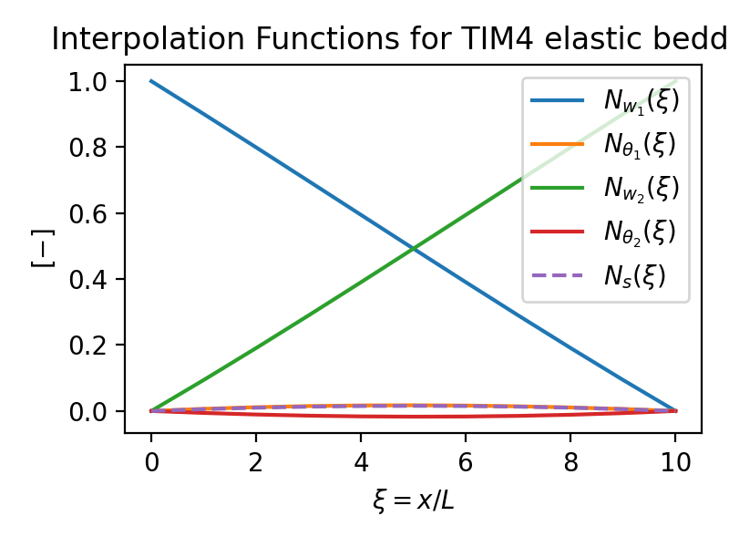
The following figure illustrates the interpolation functions for the response quantities of a standard TIM4 element:

The interpolation functions for the response quantities of a TIM4 element on the elastic ballast is illustrated as:
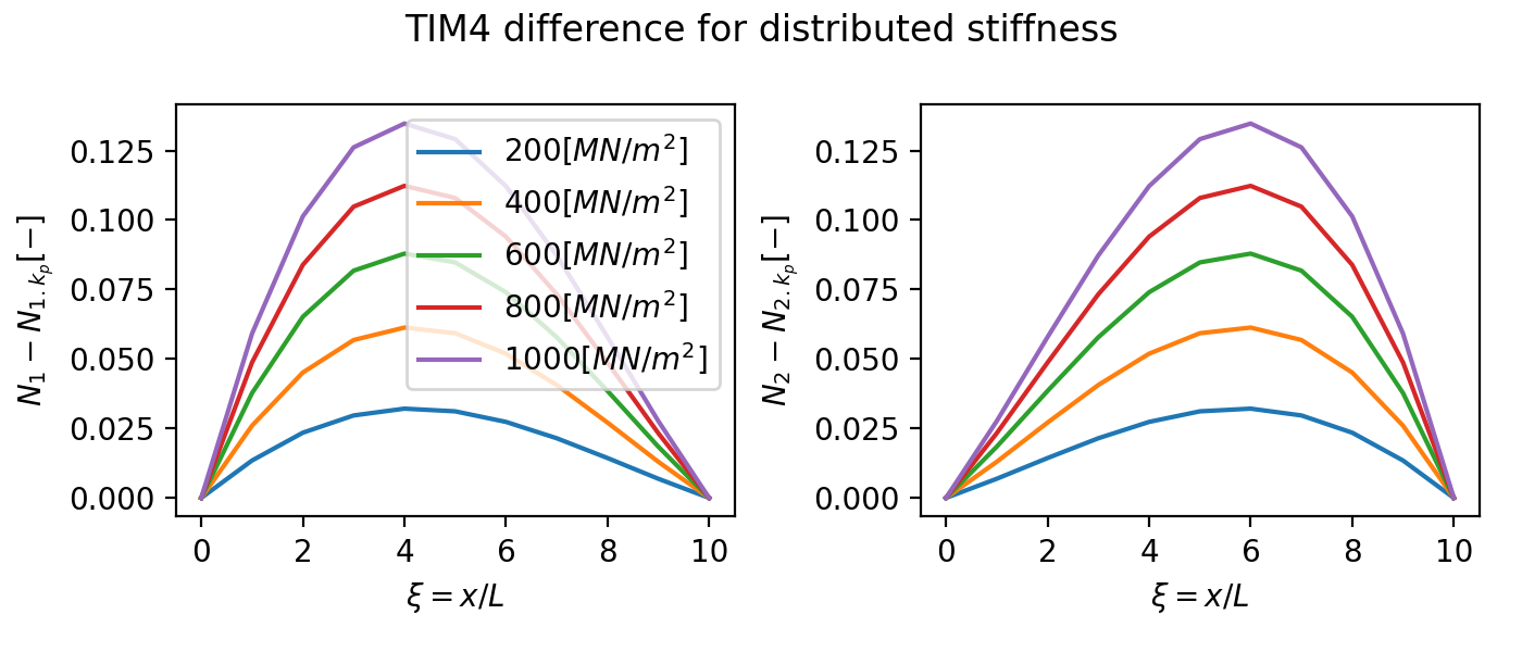
The difference between the TIM4 and TIM4eb at changing stiffness can be illustrated as:
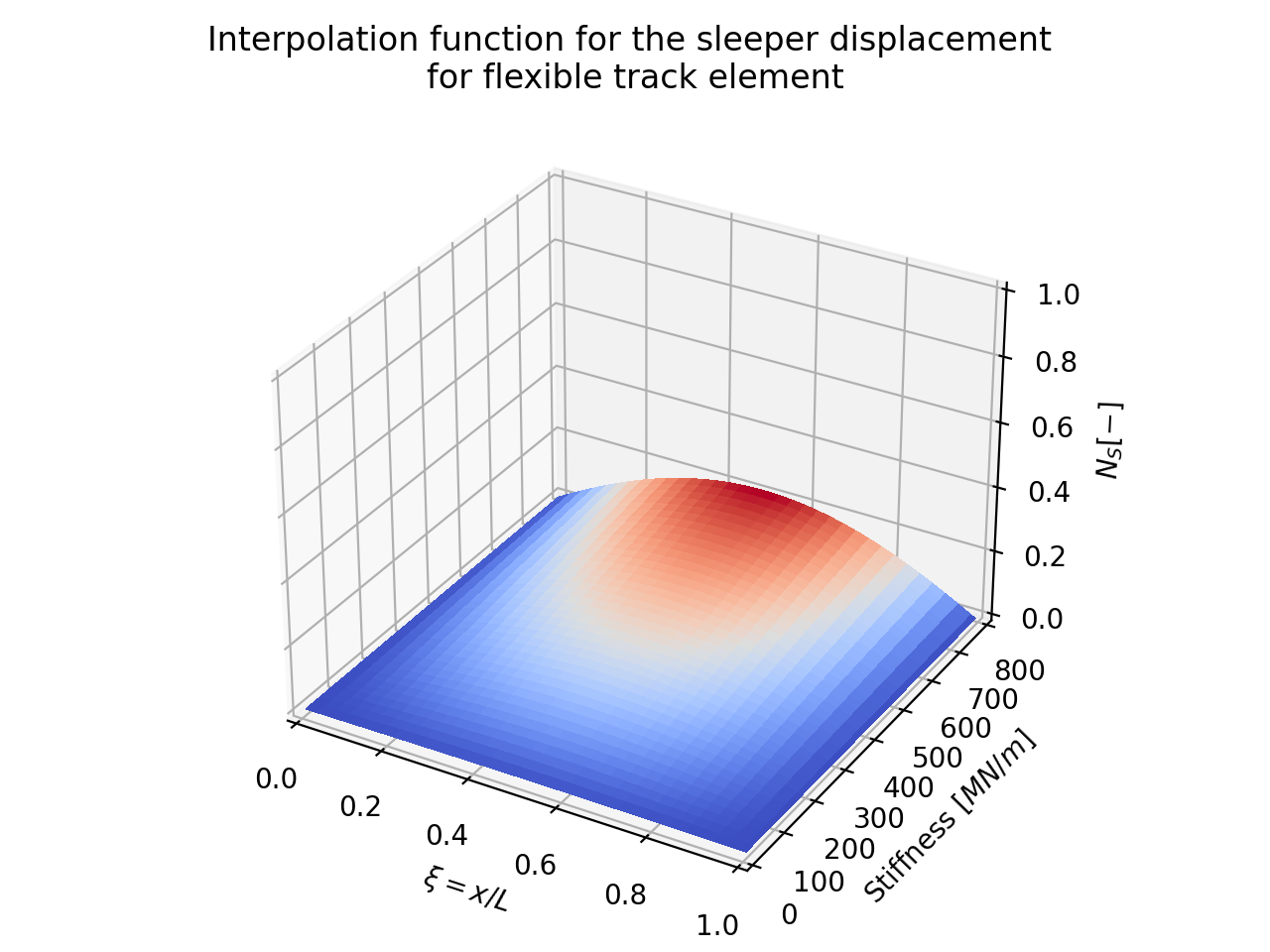
Influence of the sleeper stiffness on the interpolation function for the sleeper displacement:
Track Frequency Response Evaluation
This example evaluates the frequency response of a track composed of TIM4 or TIM4eb (eb: elastic bedding) elements using the github example code.
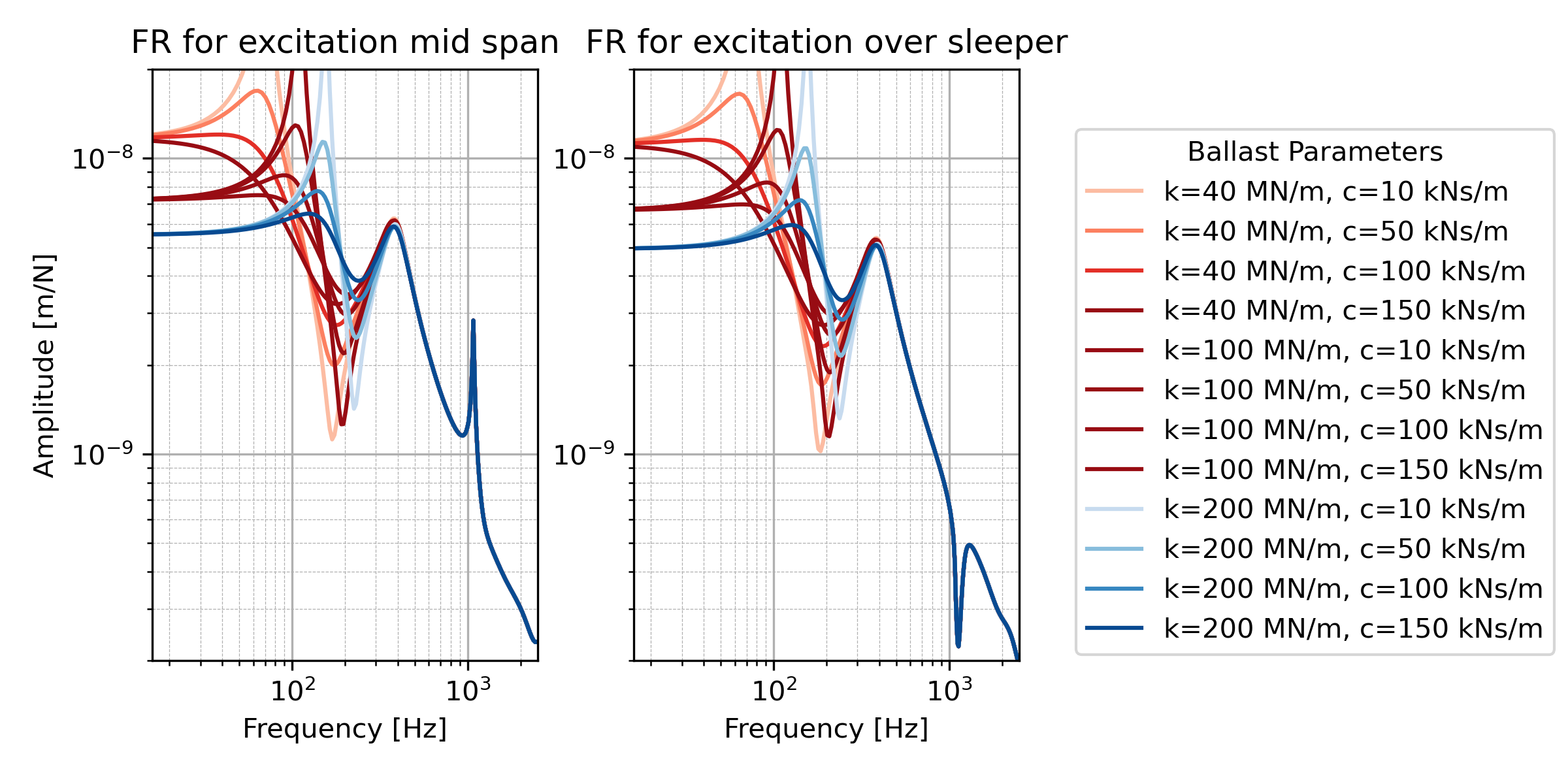
Frequency response of the track for point excitation at mid-span or over the sleeper for changing ballast pameters:
Frequency response of the track for point excitation at mid-span or over the sleeper for changing pad pameters:

Frequency response observed at different DOFs of the track for point excitation at mid-span or over the sleeper compared for PT (TIM4) and EB (TIM4eb):

Frequency response observed at different DOFs of the track for point excitation at mid-span or over the sleeper compared for PT (TIM4) and EB (TIM4eb):
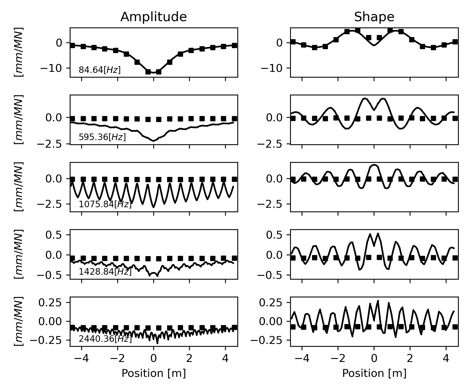
Modal response amplitude and shapes for mid-span excitation at peak response frequencies (peak picking on the FRF):
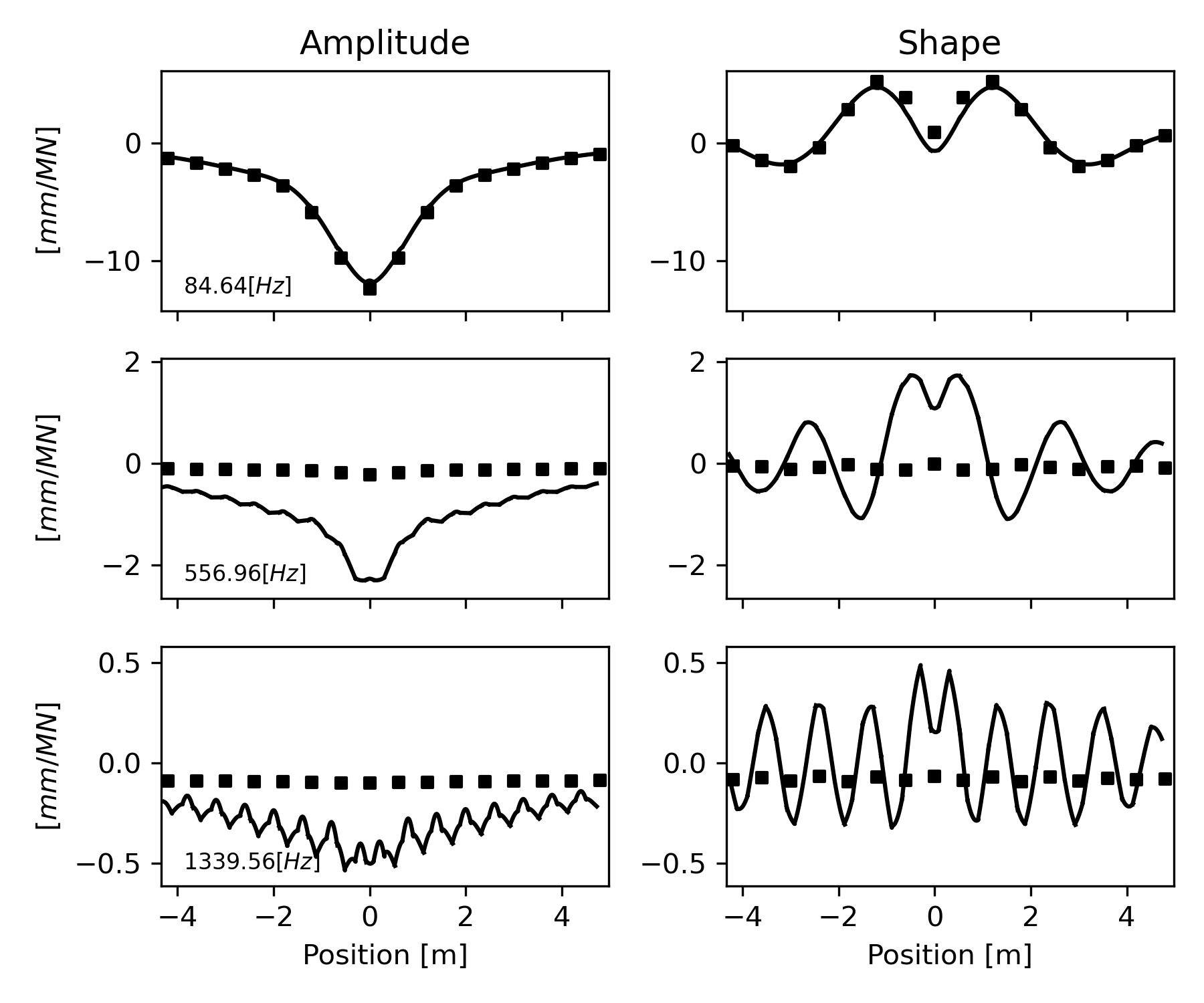
Modal response amplitude and shapes for excitation over the sleeper at peak response frequencies (peak picking on the FRF):
Time integration for impulse
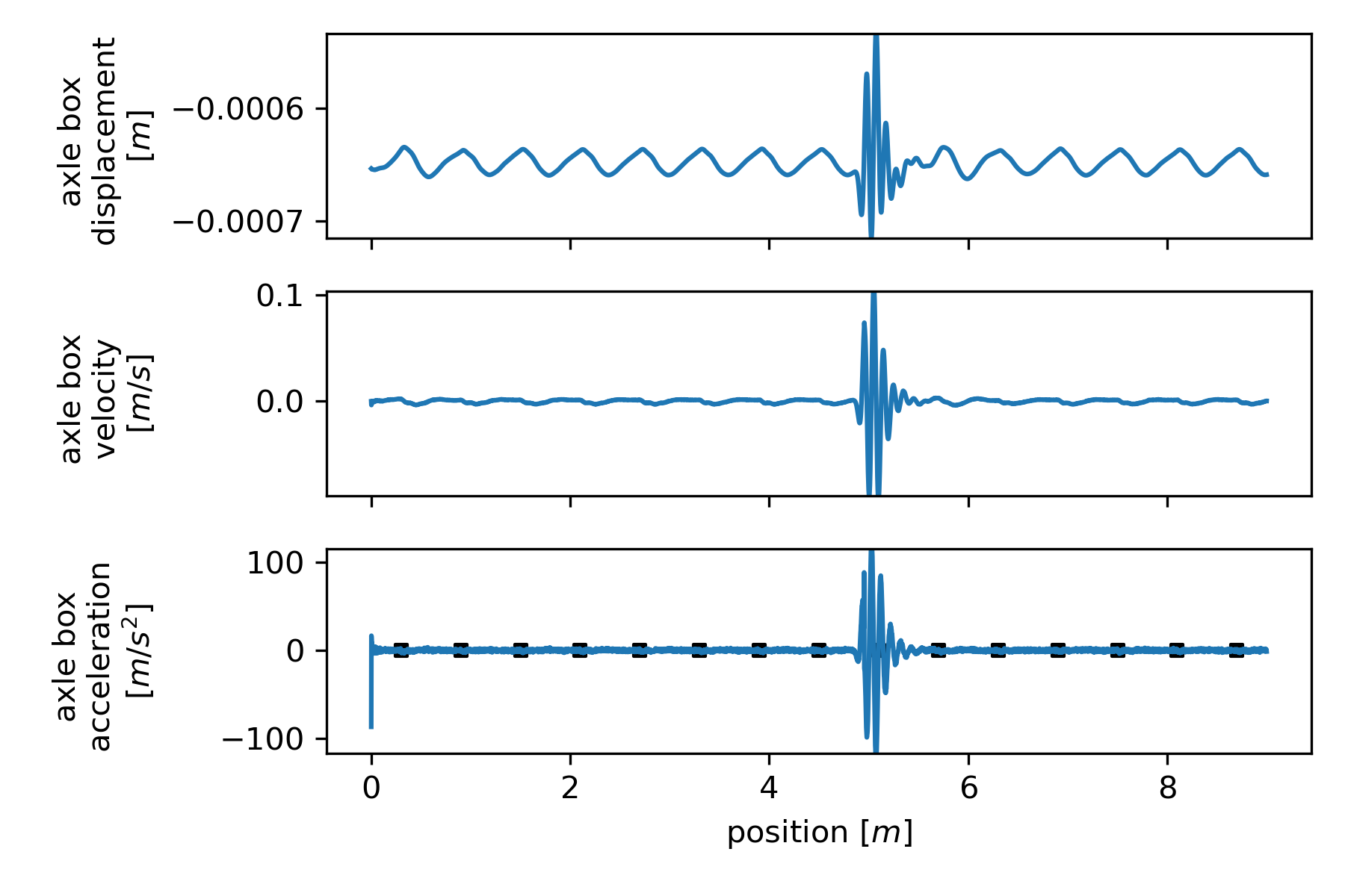
This example evaluates the response of the axle during the crossing of a vehicle with the parameters of an EW4 Panorama waggon using the github example code.
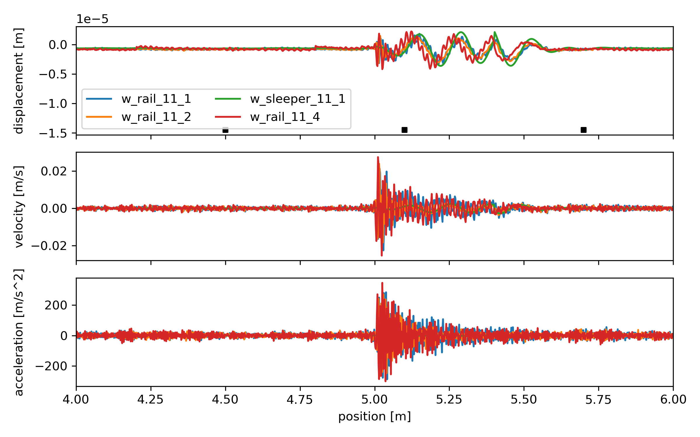
Time series of the axle response for the crossing of a defect after 0.25 seconds:
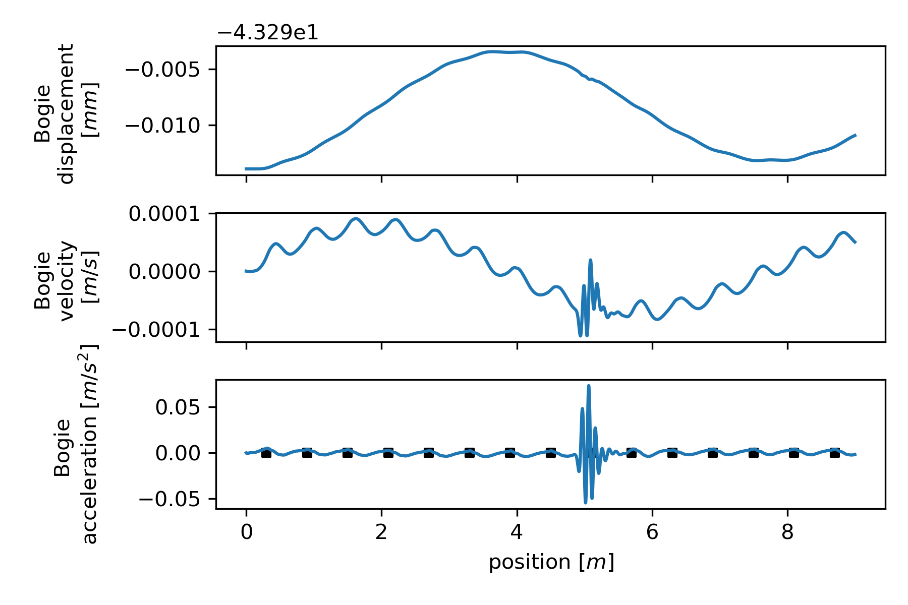
Time series of the bogie response for the crossing of a defect after 0.25 seconds:
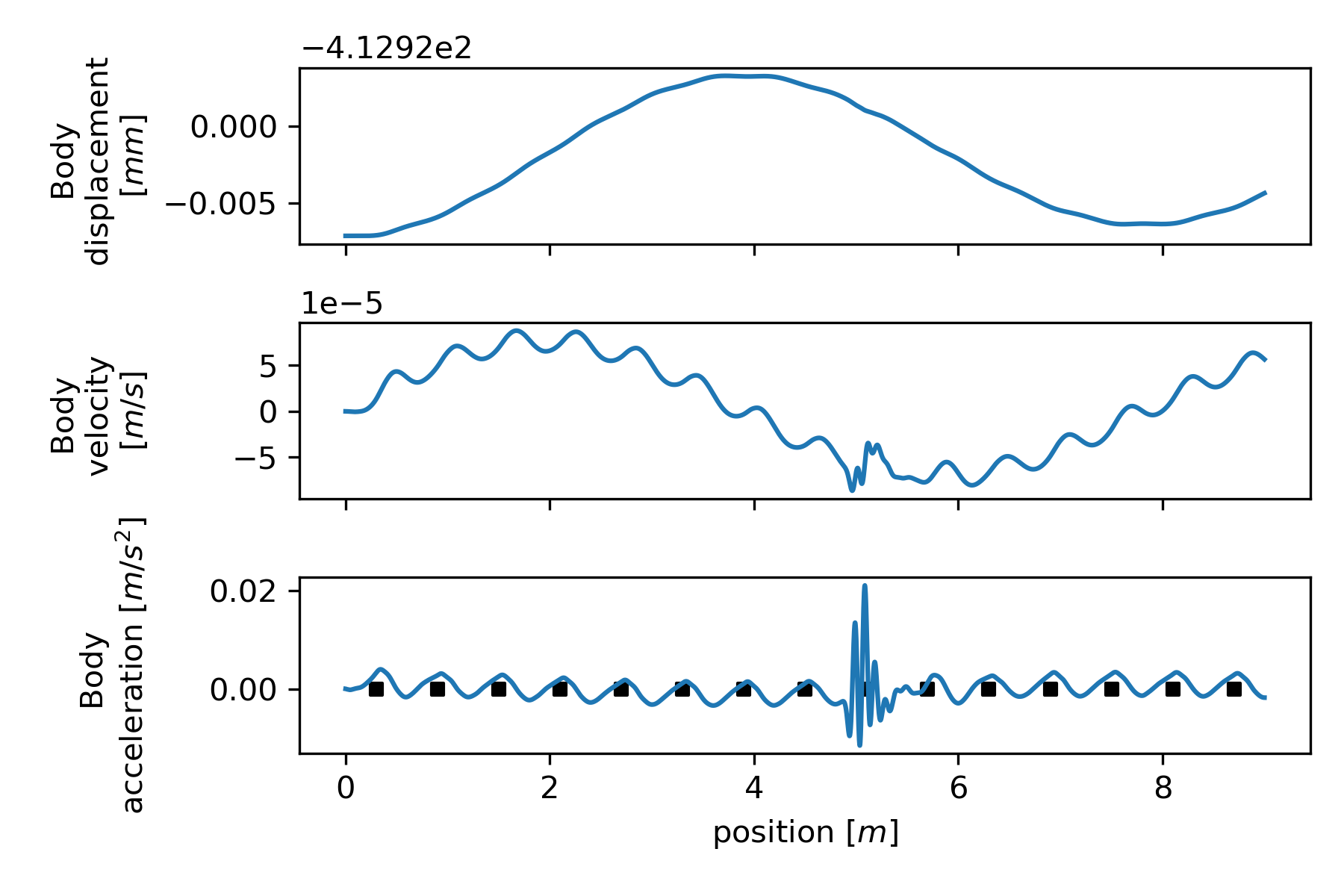
Time series of the body response for the crossing of a defect after 0.25 seconds:
Frequency response observed at different DOFs of the track for point excitation at mid-span or over the sleeper compared for PT (TIM4) and EB (TIM4eb):
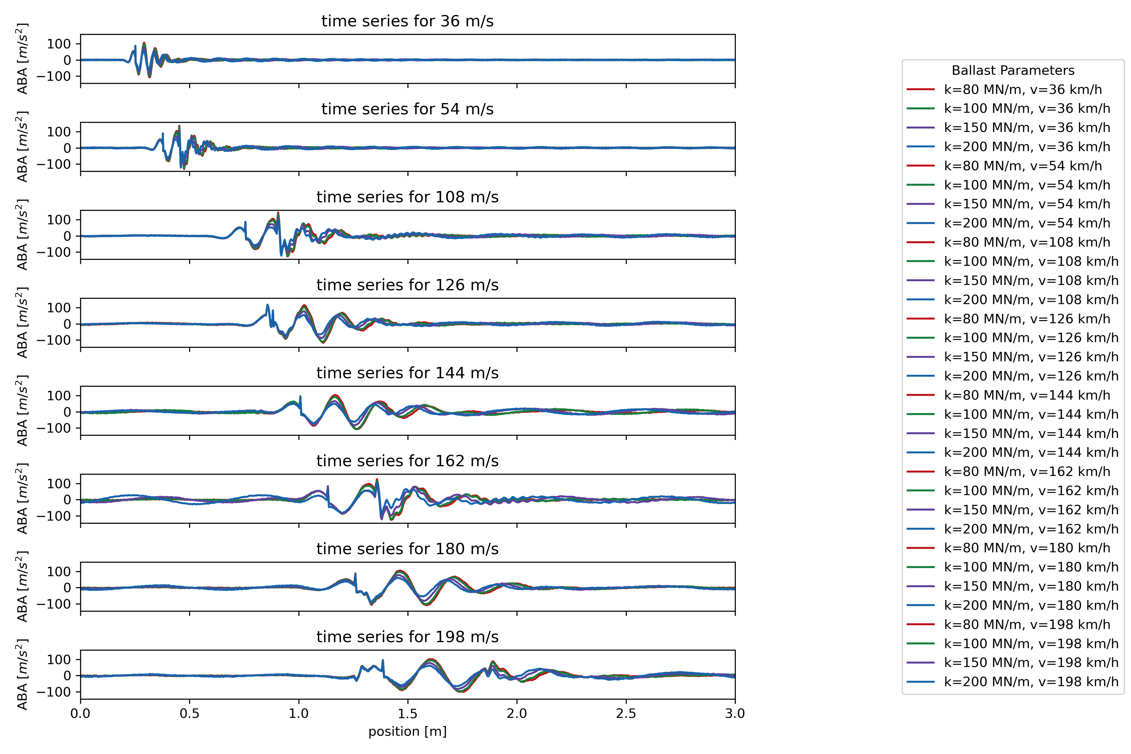
Time integration with varying track parameters
This example evaluates the response of the system during the crossing of a vehicle with the parameters of an EW4 Panorama waggon using the github example code.
Time series of the axle response for the crossing of a defect after 0.25 seconds at varying speeds: